Since the digit lenses are made of acrylic, any strike from a ball would likely shatter them. So a 3mm polycarbonate sheet has been used to cover the front of the board. The architrave was again fitted by Neil Gaffan of Eco-Lutions Building Services. The architrave needs treating or painting, but VPs day is nearly upon us!
Finally, the built board is heavy and unwieldy. Since the case was pretty rigid on its own, I made a rudimentary trolley using a simple softwood frame and trolley wheels (again the wood needs painting).
With the box primed and painted, the digits made and the cricket season already beginning I set my sights on Ickleton CC’s annual VP’s day as a target for the scoreboard debut.
First I constructed a ‘control panel’ to hold the old Linksys router I had at home, the Raspberry Pi, Arduino, extension lead and the 240V to 12V converter. Connecting all the parts up allowed a quick test of the website. Having crossed everything nothing blew and no magic smoke appeared. Success!
Having fixed the control panel to the inside of the case, I set about fixing each set of digits in place. I used corner joints to fix the digit block to the case taking care to ensure the digits were centered in the case opening.
Digits fitted, I wired up the control panel to the digits and tested everything. Then, drilling a hole in the rear of the case I changed the extension lead plug for a caravan/camping style 3 pin connector.
Finally, I measured up and applied the vinyl lettering – printed and cut by local company Alan Drury Signwriting. Following his instructions the lettering was easily applied, and looks great.
Another awesome member of Ickleton CC, being a builder by trade, offered to build the box for me. Using the plans provided by Stalybridge St. Paul’s Cricket Club (SSPCC) site he built the box using 12mm ply and some internal struts for support. Massive thanks to Neil Gaffan of Eco-Lutions Building Services in Saffron Walden for this amazing case.
I created a test circuit using a breadboard, Arduino Uno. Then made initial test digits on cardboard (picture) using both tape LED’s and connectors and pre-made segment LED’s. I found the pre-made segments gave a much more reliable connection so opted to use those for the full build. Other components were sourced from Ebay (capacitors, shifter chips, 12V-5V stepdown) .
Digit Circuits
The remainder of the shifter chips were obtained from Farnell, with the sockets coming from Ebay. The trade off in price/ease of use between strip board and purpose made PCB was so negligible I opted for the ease of effort and found PCBs on Ebay. Wire was also sourced from Ebay (I really should see about some sponsorship) via choicecables-uk since they offered many length and colour choices.
The remainder of the shifter chips were obtained from Farnell, with the sockets coming from Ebay. The trade off in price/ease of use between strip board and purpose made PCB was so negligible I opted for the ease of effort and found PCBs on Ebay. Wire was also sourced from Ebay (I really should see about some sponsorship) via choicecables-uk since they offered many length and colour choices.
Circuit Spaghetti… again
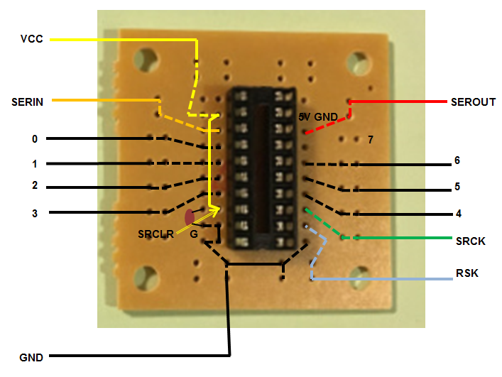
Over the course of the longer winter nights I managed to find time (and incredible patience of my heavily pregnant other half) to solder all the circuits according to this helpful diagram found hiding amongst the Forum on the buildyourownscoreboard site. For ease of connection later on, I made sure each wire was stripped at both ends before soldering and labelled all wires! I ended up with a satisfyingly colourful tub of circuit spaghetti. Circuits were then sprayed with Conformal Coating in order to protect them from the elements.
Digit Mounts
I used MDF for the back of digit mounts. Working from the plans provided on the Stalybridge St. Paul’s Cricket Club (SSPCC) site, adding 20mm each side. Using yet another cereal packet I made a template to map out LED module locations (using the digit layout again provided by the SSPCC site). I drilled small holes for the wires to push through to the back. I treated soft wood for use as the digit edges and as a backing for the acrylic digit lenses.
I used nylon screws and nuts to fix the circuit boards to the rear of the digit case. Take care when cutting the wires you don’t require on the LED modules. I went through a couple of spares through lack of due care and attention!
Digit Lenses
I sourced cut to size sheets of 3mm frosted (matt) black and orange tinted acrylic from www.sheetplastics.co.uk. Using the amazing facilities at Cambridge MakeSpace and a lot of help from Mahdi Mahmoudy we laser cut the sheets. The orange only required screw holes and was mounted directly behind the black which had the digit segments cut out. I was really pleased with the finish this gave, and using a laser cutter was a lot of fun.
The Raspberry Pi acts as a server for the website and is also home to the REST API that acts as the layer between website and Arduino. I had an old Raspberry Pi Model B and case hanging around so I used that. Since this project doesn’t require a high specification I’ve experienced no issues so far.
Website
Since I wanted to learn React this seemed a good project to get my teeth into. My intention was to create a site that both replicated the scoreboard in appearance but was also adaptive enough to be used in portrait mode on a phone. An example of the site I came up with can be seen here. The full code for the site is available on github.
REST API
The rest API is written in Python using the Flask microframework . It is intentionally minimal and hopefully easily used by others undetaking a similar project. Code can be found here.
Having never programmed an Arduino, but having some knowledge of the C Language made this task easier for me. Having read and understood the Arduino code linked in the Westbury On Severn site I dug a little deeper into the imported modules and found that the CmdMessenger module had been updated (see code here) and that this tied in nicely with PyCmdMessenger (I had python in mind for the REST API). I’ve included the code below.
/* *
 *
 * Name: ickleton_scoreboard.pde
 * Author: David Jones (drjdev@github.com)
 *
 * Scoreboard software, based on ideas from https://buildyourownscoreboard.wordpress.com
 * Takes input from RPi and outputs information to
 * shifter chips to light numbers on a cricket scoreboard
 *
 * Acknowledgements:
 *  CmdMessenger.h - https://github.com/thijse/Arduino-CmdMessenger
 *  */

// CmdMessenger(3) library available from https://github.com/thijse/Arduino-CmdMessenger
#include <CmdMessenger.h>

// Base64 library available from https://github.com/adamvr/arduino-base64
//#include <Base64.h>

// Streaming4 library available from http://arduiniana.org/libraries/streaming/
//#include <Streaming.h>

// Library to control shifters courtesy of http://www.proto-pic.com/Resources/shifter.zip
// Modified to take strings rather than int
#include <ShifterStr.h>

// Setup the field separators for CmdMessenger
char field_separator = ',';
char command_separator = '#';

// Attach a new CmdMessenger object to the default Serial port
CmdMessenger cmdMessenger = CmdMessenger(Serial, field_separator, command_separator);

// set up the char arrays for each scoreboard section
char *batAScore = "   ";// = { '\0' };
char *batBScore = "   ";//[4] = { '\0' };
char *total = "   ";//[4] = { '\0' };
char *wickets = " ";//[2] = { '\0' };
char *overs = "  ";//[3] = { '\0' };
char *target = "   ";//[4] = { '\0' };

char batAScoreStr[] = "Bat A Score";
char totalScoreStr[] = "Total Score";
char batBScoreStr[] = "Bat B Score";
char wicketsStr[] = "Wickets";
char oversStr[] = "Overs";
char targetScoreStr[] = "Target Score";

// Setup shifters
Shifter shifterSet1(9,2,3,4);
Shifter shifterSet2(6,5,6,7);

// This is the list of recognized commands. These can be commands that can either be sent or received.
// In order to receive, attach a callback function to these events
enum
{
  // Commands
  kAcknowledge        ,  // Command to acknowledge that cmd was received
  kTest1Ack        ,
  kError              ,  // Command to report errors
  kArduinoReady       ,  // Command to confirm Arduino is ready
  kTestMode1           ,  // Command to enter test mode
  kUpdateScoreboard   ,  // Command to request update of scoreboard
  kScoreboardUpdated  ,  // Command to return updated scores
  kGetCurrentScore    ,  // Command to retrieve current score stored on Arduino
  kReturnCurrentScore ,  // Command to return current score stored on Arduino
};

// ------------------  C A L L B A C K S -----------------------

// Commands we send from the Arduino to be received on the PC

// ------------------ C A L L B A C K  M E T H O D S -------------------------


void test_mode1()
{
    char buf[] = { "Test Mode Set" };
    cmdMessenger.sendCmdStart(kTest1Ack);
    cmdMessenger.sendCmdArg(buf);

    shifterSet1.display("111333222");
    shifterSet2.display("445678");
    cmdMessenger.sendCmd(kTest1Ack, buf);

    //char test_comp[] = { "Test complete" };
    //cmdMessenger.sendCmdArg(test_comp);
    cmdMessenger.sendCmdEnd();
}

void return_current_score()
{
    cmdMessenger.sendCmdStart(kReturnCurrentScore);
    cmdMessenger.sendCmdArg(batAScore);
    cmdMessenger.sendCmdArg(total);
    cmdMessenger.sendCmdArg(batBScore);
    cmdMessenger.sendCmdArg(wickets);
    cmdMessenger.sendCmdArg(overs);
    cmdMessenger.sendCmdArg(target);
    cmdMessenger.sendCmdEnd();
}

void update_scoreboard()
{
    char scoreStringTop[10] = { '\0' };
    char scoreStringBottom[7] = { '\0' };

    //Read all score strings
    batAScore = cmdMessenger.readStringArg();
    total = cmdMessenger.readStringArg();
    batBScore = cmdMessenger.readStringArg();
    wickets = cmdMessenger.readStringArg();
    overs = cmdMessenger.readStringArg();
    target = cmdMessenger.readStringArg();


    //Bat A Score retrieval
    strcpy(scoreStringTop,batAScore);

    cmdMessenger.sendCmdStart(kScoreboardUpdated);
    cmdMessenger.sendCmdArg(batAScoreStr);
    cmdMessenger.sendCmdArg(batAScore);


    //Total score retrieval
    strcat(scoreStringTop,total);

    cmdMessenger.sendCmdArg(totalScoreStr);
    cmdMessenger.sendCmdArg(total);

    //Bat B Score retrieval
    strcat(scoreStringTop,batBScore);

    cmdMessenger.sendCmdArg(batBScoreStr);
    cmdMessenger.sendCmdArg(batBScore);

    shifterSet1.display(scoreStringTop);

    memset(scoreStringTop, '\0', 10);
    memset(scoreStringBottom, '\0', 7);

    //Overs
    strcpy(scoreStringBottom, overs);

    cmdMessenger.sendCmdArg(oversStr);
    cmdMessenger.sendCmdArg(overs);

    //Retrieve Wickets
    strcat(scoreStringBottom, wickets);

    cmdMessenger.sendCmdArg(wicketsStr);
    cmdMessenger.sendCmdArg(wickets);

    //Target Score
    strcat(scoreStringBottom, target);

    cmdMessenger.sendCmdArg(targetScoreStr);
    cmdMessenger.sendCmdArg(target);
    cmdMessenger.sendCmdEnd();

    shifterSet2.display(scoreStringBottom);
}


// ------------------ D E F A U L T  C A L L B A C K S -----------------------

// Commands we send from the PC and want to recieve on the Arduino.
// We must define a callback function in our Arduino program for each entry in the list below vv.
// They start at the address kSEND_CMDS_END defined ^^ above as 004
/*
messengerCallbackFunction messengerCallbacks[] =
{
  update_scoreboard, //004
  test_mode, //005
  NULL
};
*/
// Its also possible (above ^^) to implement some symetric commands, when both the Arduino and
// PC / host are using each other's same command numbers. However we recommend only to do this if you
// really have the exact same messages going in both directions. Then specify the integers (with '=')

// Called when a received command has no attached function
void OnUnknownCommand()
{
  cmdMessenger.sendCmd(kError,"Command without attached callback");
}

// Callback function that responds that Arduino is ready (has booted up)
void OnArduinoReady()
{
  cmdMessenger.sendCmd(kAcknowledge,"Arduino ready");
}

// ------------------ E N D  C A L L B A C K  M E T H O D S ------------------

// Commands we send from the PC and want to receive on the Arduino.
// We must define a callback function in our Arduino program for each entry in the list below.

void attachCommandCallbacks()
{

  cmdMessenger.attach(kUpdateScoreboard, update_scoreboard);
  cmdMessenger.attach(kTestMode1, test_mode1);
  cmdMessenger.attach(kGetCurrentScore, return_current_score);
  // Attach callback methods
  cmdMessenger.attach(OnUnknownCommand);
}

void setup()
{
  // Listen on serial connection for messages from the pc
  Serial.begin(115200); // Arduino Uno, Mega, with AT8u2 USB

  // Adds newline to every command
  cmdMessenger.printLfCr();

  // Attach my application's user-defined callback methods
  attachCommandCallbacks();


  //Initialise display to zeroes.
  //First show all 8's to check LEDs
  shifterSet1.display("888888888");
  shifterSet2.display("888888");
  delay(5000);
  //Then...
  shifterSet1.display("--0--0--0");
  shifterSet2.display("-00---");


  // Send the status to the PC that says the Arduino has booted
  cmdMessenger.sendCmd(kAcknowledge,"Arduino has started!");
 }


// ------------------ M A I N ( ) --------------------------------------------

// Timeout handling
long timeoutInterval = 2000; // 2 seconds
long previousMillis = 0;
int counter = 0;

void timeout()
{
  // blink
  if (counter % 2)
    digitalWrite(13, HIGH);
  else
    digitalWrite(13, LOW);
  counter ++;
}

void loop()
{
  // Process incoming serial data, if any
  cmdMessenger.feedinSerialData();

  // handle timeout function, if any
  if (  millis() - previousMillis > timeoutInterval )
  {
    timeout();
    previousMillis = millis();
  }

  // Loop.
}
Having read through the Westbury on Severn site and seen their work. This looked like a project I could take on. I needed to learn some front end development skills for work, so the opportunity to build a site to control the scoreboard appealed. I had already messed around with a Raspberry Pi and this project also gave me the opportunity to learn how to use the Arduino, along with a chance to build the electronics and gain some new skills in woodwork.
The way I see it I can break this project down into 4 parts (assuming you want to make work for yourself like me and don’t reuse the Arduino code and web site code).
Joining Ickleton CC in 2018 was a new venture. Having been interested in and followed cricket for some time, I was unsure as to how I would be received given I had never played competitive cricket before.
A handful of games over the previous couple of years (mostly out of sympathy) with a friendly work side. Combined with a few hours stood on a boundary during a sports lesson decades ago were the sum total of my previous experience. On previous years I had ventured to play a couple of friendly games with the Ickelton C.C. after the friendly 20:20 season ended, but my internal competitive side wanted more.
Novice in action
Over the course of the 2018 season there were conversations around various potential improvements to the club. One of which was the possibility of an electronic scoreboard. Given I am a bit of a tinkerer and enjoy a new challenge, I decided to research DIY electronic scoreboards. This led me to discover the awesome project undertaken by the guys at Westbury on Severn Cricket Club which has been successfully replicated and built on by several other clubs (and sports) as can be seen on their site.
The idea seed had been sown.
Apologies for the lack of DIY scoreboard content in this first post. I felt setting the scene was part of the story.