
I created a test circuit using a breadboard, Arduino Uno. Then made initial test digits on cardboard (picture) using both tape LED’s and connectors and pre-made segment LED’s. I found the pre-made segments gave a much more reliable connection so opted to use those for the full build. Other components were sourced from Ebay (capacitors, shifter chips, 12V-5V stepdown) .
Digit Circuits
The remainder of the shifter chips were obtained from Farnell, with the sockets coming from Ebay. The trade off in price/ease of use between strip board and purpose made PCB was so negligible I opted for the ease of effort and found PCBs on Ebay. Wire was also sourced from Ebay (I really should see about some sponsorship) via choicecables-uk since they offered many length and colour choices.
The remainder of the shifter chips were obtained from Farnell, with the sockets coming from Ebay. The trade off in price/ease of use between strip board and purpose made PCB was so negligible I opted for the ease of effort and found PCBs on Ebay. Wire was also sourced from Ebay (I really should see about some sponsorship) via choicecables-uk since they offered many length and colour choices.

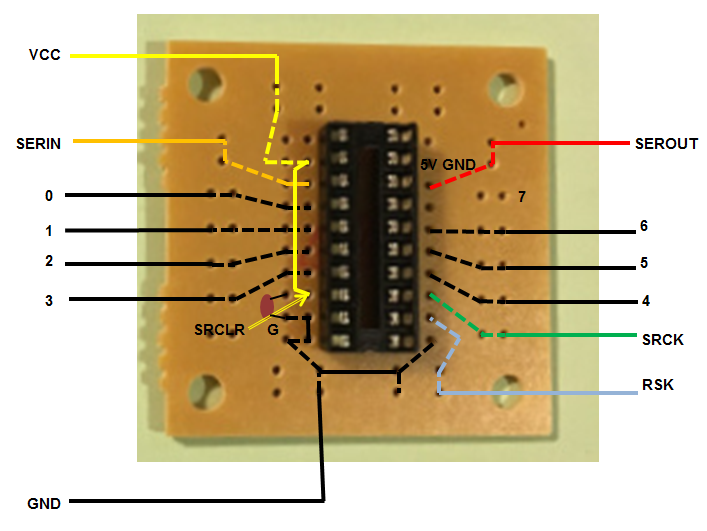
Over the course of the longer winter nights I managed to find time (and incredible patience of my heavily pregnant other half) to solder all the circuits according to this helpful diagram found hiding amongst the Forum on the buildyourownscoreboard site. For ease of connection later on, I made sure each wire was stripped at both ends before soldering and labelled all wires! I ended up with a satisfyingly colourful tub of circuit spaghetti. Circuits were then sprayed with Conformal Coating in order to protect them from the elements.
Digit Mounts
I used MDF for the back of digit mounts. Working from the plans provided on the Stalybridge St. Paul’s Cricket Club (SSPCC) site, adding 20mm each side. Using yet another cereal packet I made a template to map out LED module locations (using the digit layout again provided by the SSPCC site). I drilled small holes for the wires to push through to the back. I treated soft wood for use as the digit edges and as a backing for the acrylic digit lenses.

I used nylon screws and nuts to fix the circuit boards to the rear of the digit case. Take care when cutting the wires you don’t require on the LED modules. I went through a couple of spares through lack of due care and attention!
Digit Lenses
I sourced cut to size sheets of 3mm frosted (matt) black and orange tinted acrylic from www.sheetplastics.co.uk. Using the amazing facilities at Cambridge MakeSpace and a lot of help from Mahdi Mahmoudy we laser cut the sheets. The orange only required screw holes and was mounted directly behind the black which had the digit segments cut out. I was really pleased with the finish this gave, and using a laser cutter was a lot of fun.


One thought on “Creating The Digits”